

How works a Frequency Modulated Continuous Wave Radar Sensor
Frequency Modulated Continuous Wave Radar (FMCW)
Basic operating principles and theory
In this period, at ACE Innovation, we are working on FMCW Radar for some applications about landslide detection, water level detection in river and, more in general, about distance detection with high resolution. In this post, and others in near future, we want write about FMCW radar. These articles have been thinking for academic studends or everyone knows a little of math.
FMCW (Frequency Modulated Continuous Wave) radar differs from pulsed radar in that an electromagnetic signal is continuously transmitted. The frequency of this signal changes over time, generally in a sweep across a set bandwidth. The difference in frequency between the transmitted and received (reflected) signal is determined by mixing the two signals, producing a new signal which can be measured to determine distance or velocity. A sawtooth function is the simplest, and most often used, change in frequency pattern for the emitted signal.
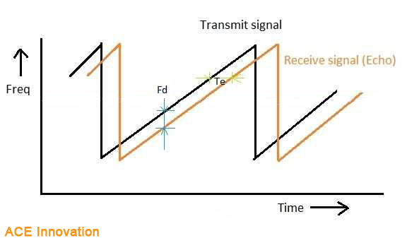
Figure 1: Emitted signal with frequency slope kf, frequency sweep bandwidth BW and frequency sweep time T
Frequency Modulated Continuous Wave radar differs from classical pulsed radar systems in that an RF signal is continuously output. Consequently, time of flight (ToF) to a reflecting object can not be measured directly. Instead, the FMCW radar emits an RF signal that is usually swept linearly in frequency. The received signal is then mixed with the emitted signal and due to the delay caused by the time of flight for the reflected signal, there will be a frequency difference that can be detected as a signal in the low frequency range. A schematic presentation is shown in Figure 2.
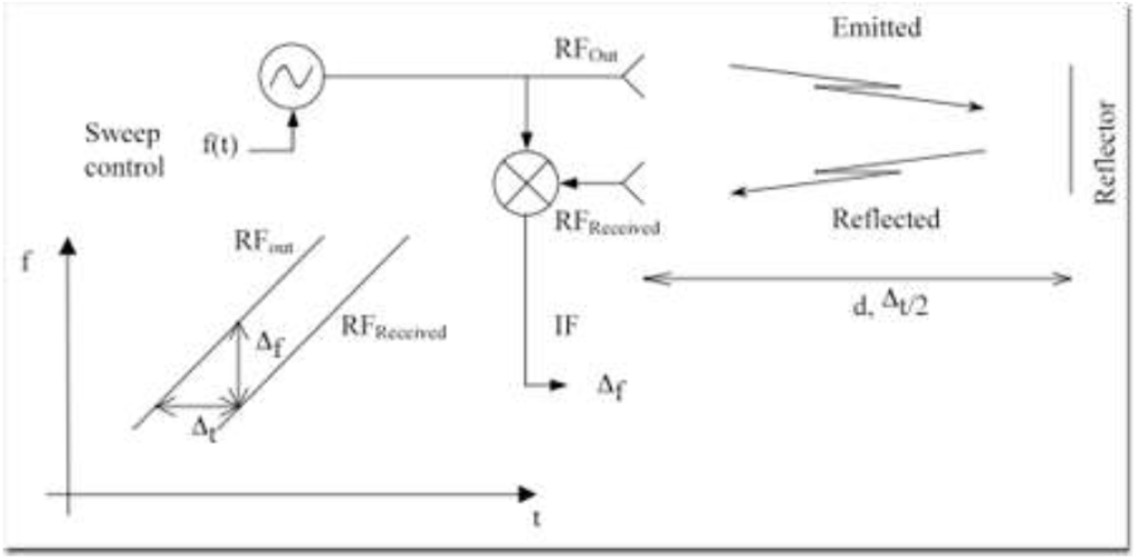
Figure 2: Schematic presentation showing how a low frequency signal is generated by mixing the received RF signal with the output RF signal. Due to the delay, Δt, caused by emitted signal traveling the distance to the reflector and back to the receiver, there will be a small difference in signal frequency between the two RF signals. This is output as an IF-signal with frequency Δf.
A simplified derivation of the intermediate frequency (IF) signal with the frequency Δf can be made in the following way: assume that the RF signal generator will output a frequency that is changing linearly over time as:
\(f_{RFOut} = F_{RF0}+k_f*t,\: 0\leq t<T\)
where \(f_{RF0}\) is the starting frequency, T is the frequency sweep time and \(k_{f}\) is the slope of the frequency change, i.e. the sweep rate:
\(k_f = \frac{BW}{T}\)
where BW is the frequency sweep bandwidth.
The delay caused by the round-trip of the emitted signal to the reflector is calculated as:
\(\Delta t = 2 \: \frac{d}{c}\)
where d is the distance between the radar antenna and the reflector and c is the speed of light.
Due to the delay, the frequency of the received signal compared with the emitted signal will be:
\(f_{RFReceived} = f_{RF0}+k_f*(t – \Delta t), \: \Delta t \leq t <(T+ \Delta t)\)
The difference in frequency, Δf, between \(f_{RFReceived}\) and \(f_{RF0}\) is thus:
\(\Delta f = k_f * (- \Delta t)\)
This is the signal that is output from the detector. The minus sign can be omitted since the real signal frequency output from the radar detector is wrapped to a positive frequency. Thus the expression can be written as:
\(\Delta f = \frac{BW}{T}\cdot 2 \: \frac{d}{c}\)
In the next article a simple example and more details.


